How to Use SILIMER 5091 for Better Processing?
SILIMER 5091 can support smoother polymer processing, but results depend on the resin, dosage, and operating conditions. A careful trial begins with the material itself: note the resin grade, check the recommended addition range, and record melt temperature, screw speed, and output. Keep the baseline run. It gives you something real to compare against. Small changes matter. A cleaner die face, steadier extrusion pressure, or fewer visible flow marks can provide useful clues, though none alone proves that the additive caused the improvement.
For an illustrative expert perspective, fictional polymer-processing specialist Dr. Elena Morris puts the guiding idea this way: “Treat every additive trial as a controlled comparison, not a guess.” This is an editorially written line, not a verified quotation from a real expert. In practice, introduce SILIMER 5091 evenly and avoid changing several process settings at once. Watch the melt and finished surface, then log results across repeat runs. One trial may look promising and still fail to repeat. That deserves attention, not a polished claim. This guide explains how to prepare a trial, tune addition and processing conditions, and assess performance with practical observations. Check current supplier guidance for product-specific handling and compatibility before use.
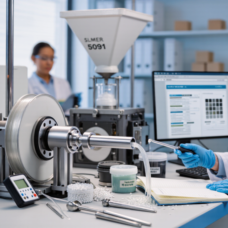
Verify SILIMER 5091’s Resin Compatibility and TDS-Recommended Loading
Better processing starts with a compatibility check, not a guess. Confirm that SILIMER 5091 is suitable for the exact resin grade and formulation. A film resin may behave differently from a molded compound, even when both share a polymer family. Review the current technical data sheet (TDS) for its recommended loading, addition method, and processing limits. If a detail is unclear, ask the supplier before scaling up.
Run a small, controlled trial at the TDS-recommended loading. Keep the resin batch, temperature, screw speed, and output rate as consistent as possible. Then observe feeding, melt pressure, die buildup, surface appearance, and any changes in the finished part. Compare results with an untreated sample. One trial may not reveal everything; colorants, fillers, or recycled content can shift performance. Record the actual settings, since production conditions rarely match a lab perfectly.
Tips: Change one variable at a time. Check dispersion and part quality, not just easier flow. A cleaner die is useful evidence, but it is not the whole result.
How to Use SILIMER 5091 for Better Processing? - Verify SILIMER 5091’s Resin Compatibility and TDS-Recommended Loading
Use the current product TDS to confirm resin compatibility and the recommended loading range before production. No product-specific compatibility or dosage values are stated below because they must be verified against that TDS.
| Resin family to check | Examples | Compatibility status | What to verify |
| Polyolefins | PE, PP | Not confirmed here; check the current SILIMER 5091 TDS. | Listed resin grades, application notes, and any restrictions. |
| Styrenic polymers | PS, ABS | Not confirmed here; check the current SILIMER 5091 TDS. | Compatibility information for the exact grade and process. |
| Engineering thermoplastics | PA, PC, PET | Not confirmed here; check the current SILIMER 5091 TDS. | TDS suitability and any resin-specific drying or processing requirements. |
| Other or modified resins | Blends, filled grades, recycled grades | Requires confirmation for the specific formulation. | Ask the supplier to confirm suitability; assess the finished part and process performance. |
| Use step | Recommended check | Record or decision |
| 1. Confirm the material | Match the exact polymer grade and application to the compatibility information in the current TDS. | Resin grade: __________
Compatibility confirmed: Yes / No |
| 2. Confirm the loading | Use the recommended loading range stated in the current SILIMER 5091 TDS. Do not assume a dosage from another resin or application. | TDS loading range: __________
Selected trial loading: __________ |
| 3. Calculate the amount | For a loading expressed as a percentage of total blend: additive mass = total blend mass × loading percentage ÷ 100. | Example calculation: 100 kg blend at 1% loading = 1 kg additive. |
| 4. Run a controlled trial | Keep resin grade, equipment settings, and other ingredients consistent when comparing a trial with a control batch. | Compare processing stability, surface quality, and relevant finished-part requirements. |
| 5. Approve production use | Confirm the trial meets application requirements and follow the resin supplier’s processing guidance. | Approved loading and process conditions: __________ |
Important: The loading example is arithmetic only, not a recommended SILIMER 5091 dosage. Follow the current product TDS and confirm results with a controlled trial.
Select Resin-Specific Melt-Flow Conditions Using ISO 1133-1 or ASTM D1238
A processing additive can influence melt flow, but results depend on the resin and test setup. Choose conditions for the specific polymer grade, not a convenient default. ISO 1133-1 and ASTM D1238 describe methods for measuring melt mass-flow rate or melt volume-flow rate. They do not make results comparable when temperature, load, or preparation differs. Keep those details consistent.
Check the resin supplier’s technical data sheet for the recommended test temperature and load. For example, a polyolefin sample may be tested under conditions unlike those used for a higher-temperature engineering resin. Dry moisture-sensitive materials as directed, then record the drying time, temperature, and sample history. Use the same die and preheating procedure for baseline and additive-containing samples. Report the method, temperature, load, and result in g/10 min or cm³/10 min. Small differences matter. If flow changes unexpectedly, repeat the test before changing the processing recipe; a single reading can mislead.
Tips: Compare like with like. Follow either ISO 1133-1 or ASTM D1238 consistently, and document every setting. Start with the resin maker’s specified condition, then evaluate small additive adjustments. Real production may still behave differently. Check that, too.
Screen Addition Levels by Weight and Record Mixing Temperature and Time
Treat the additive level as a measured variable, not a scoop added by feel. Define the basis before weighing: for example, 0.2% by total batch weight means 4 g in a 2 kg blend. That is a calculation example, not a universal target. Use the technical guidance for the material and process, then test several levels within its stated range. Keep one batch without additive as a control. Small differences matter.
For each trial, record the additive mass, resin mass, and any other ingredients. Note the mixer type, loading order, barrel or mixing temperature, actual melt temperature if available, and mixing time. A set temperature is not always the material’s true temperature. Hold other settings steady so the comparison means something. Repeat promising trials before changing the dose. A simple table is enough, but include units and timestamps. It is easy to miss a detail when production is busy. Our worksheet can still be imperfect; recording an unexpected result is better than quietly leaving it out. Compare surface appearance, flow, pressure, and any sticking or buildup, then adjust one variable at a time.
Compare Die Pressure, Torque, and Output Rate Before and After Addition
To assess whether a processing aid improves extrusion, compare die pressure, screw torque, and output rate under matched conditions. Keep the resin lot, screw speed, temperature profile, and feed rate consistent. Record a stable baseline before adding the material. Then introduce the recommended amount gradually and allow the line to settle. Note the pressure reading, motor load, and kilograms produced per hour. Lower pressure or torque may indicate easier flow, while a higher output rate can suggest improved throughput. But one reading is not proof. Check product appearance and dimensions too.
Tips: Log readings every five minutes. Change one setting at a time. Keep samples from both runs.
A practical comparison should include a repeat run, since startup variation can distort results. Watch for surging, die buildup, or surface changes during a longer trial. If pressure falls but output stays flat, the aid may still reduce mechanical load; it may not increase production. Results depend on the formulation and equipment. Small differences can also come from temperature drift or inconsistent feeding. Be candid about those limits in the trial record. A neat table helps, but it cannot explain every fluctuation.
Measure Film Friction Using ASTM D1894 and Compare COF Results
Film friction is measurable, not guesswork. ASTM D1894 measures static and kinetic coefficients of friction (COF) for plastic film and sheeting. The standard defines a test method, not a universal “good” COF value. Condition samples consistently, following ASTM D618 where applicable, and record temperature, humidity, film side, direction, sled, and test speed.
Run three replicates. Small differences matter. A hypothetical comparison might show untreated film at 0.38 static and 0.31 kinetic COF, versus additive-treated film at 0.24 and 0.20. These figures are illustrative, not published industry benchmarks. Calculate the change from your own ASTM D1894 laboratory report, and compare like-for-like specimens from the same film lot. If results vary widely, check sample conditioning and sled contact before adjusting the formulation.
A lower COF can help film move smoothly over rollers, but the lowest value is not always best. Excessive slip may affect stacking, winding, or downstream handling. Test samples after a consistent aging period, since additive migration can change friction over time. Keep the full test setup with each result; otherwise, comparisons between production runs may mislead.